
PANEL TURNING & LINE HANDLING
Automatic Panel Flipping Machines for Woodworking
Turn suitable panels to the face or orientation required by the next operation. Explore LINKYOU automatic panel flipping machines for woodworking lines, with selection based on panel size, weight, contact conditions, and infeed/outfeed layout.
Panel
Turning
Wood Panel Flipping
Line
Transfer
Defined Face Change
Panel-Based Selection
Contact Requirements
Production Layout Planning
- Quick Answer
“What Is an Automatic Panel Flipping Machine Used For?
An automatic panel flipping machine changes a workpiece’s orientation between production stages. A face-reversing operation presents the opposite surface for the next task, such as sanding or inspection. The required motion, support method, and line connection determine the suitable machine configuration.
Present the Required Face
Place the next working face in the position required by the receiving process.
Mechanize Repetitive Turning
Use a defined machine cycle for suitable turning tasks that would otherwise require manual handling.
Coordinate the Handover
Plan the output orientation and transfer position together with the downstream equipment.
- Product Range
Explore LINKYOU Panel Flipping Equipment
Explore the equipment below by its turning arrangement and intended line position. Use the product details to review a specific machine, then match the configuration to your panel, required face change, and production flow.

Barrel Turner
FB204
A ring-frame panel turner for changing the working face between production stages. Its circular frame and internal conveyor sections support a defined turning path. Review panel holding, workpiece limits, and entry/exit conditions for the proposed configuration.
Panel Flipping Machine
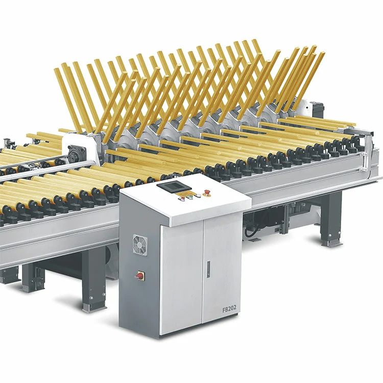
FB202
A roller-fed panel flipper with rotating support arms for transferring suitable panels through a turning station. Match the support spacing, panel stiffness, and required output orientation to the handling task and the connected production equipment.

Horizontal Panel Flipping
FB205
A panel flipping unit with opposed roller sections for a horizontal conveying line. Review the holding arrangement, turning clearance, and output face together with the upstream and downstream handover requirements.
- Turning Task
Define the Face Change and Output Orientation
Describe how the panel starts and how it must leave the station. Rotation angle alone is not enough: a turn within the horizontal plane can change the leading edge without exposing the opposite face. Mark Face A, Face B, and the travel direction when discussing a turning task.

Horizontal Panel Handling · FB205 Visualization
Face Reversal
Specify which surface must be exposed after the turn and which edge should lead into the next machine.
In-Plane Reorientation
Specify the required edge direction while confirming whether the same face should remain exposed.
Tilting or Intermediate Position
If a process needs an inclined or upright position, define that task separately and confirm that the selected equipment supports it.
Transfer Path
Show whether the workpiece must pass through, return to the infeed side, or move to another receiving position.
Not Sure Which Turning Arrangement Fits?
Send a panel photo, its size and weight, and a sketch of the required before-and-after orientation. You can begin with the task even if you do not know the machine type.
- Applications
Where Panel Flipping Fits in Production
Use a turning station where the next operation needs a different working face or orientation. The applications below describe process requirements; panel construction, contact surfaces, and line timing must be matched to the selected equipment.
Wood Door Processing
Furniture Panel Production
Between Sanding Passes
Transfer to Handling or Inspection
Please tell us if a face is freshly coated, laminated, textured, or easily marked. Contact and holding conditions need to be reviewed before selecting a turning method.
- Selection Guide
How to Select a Panel Flipping Machine?
Start with the panel, the required orientation change, and the complete operating cycle. Size and weight account for only part of the requirements; contact limits, support positions, and how panels arrive and depart are equally important to the configuration.
Factor
Information to provide
Why it matters
Panel Dimensions
Minimum and maximum length, width and thickness
Support span, opening and turning envelope
Weight and Quantity
Item weight, items per turn and total transferred load
Rated load and holding arrangement
Construction and Stiffness
Solid or composite construction, hollow sections, cut-outs, and flexibility
Suitable support and contact positions
Surface Condition
Coating, laminate, texture, dust, and areas that must not be contacted
Contact material and sample validation
Required Motion
Face A/B, leading edge, rotation axis, and output orientation / A/B
Correct turning task and mechanism
Production Demand
Panels per minute or shift, peak demand and permitted waiting time
Complete cycle and buffer requirements
Infeed and Outfeed
Conveyor heights, directions, panel gaps, and receiving positions
Handover and line coordination
Available Space
Equipment layout, turning clearance and access
Installation and movement envelope
A storage position count does not establish how many panels can be turned together. Likewise, conveyor speed is not the completed turning rate. Define the load per cycle and include positioning, holding, turning, release, and downstream waiting in the cycle review.
- Site & Interfaces
Plan the Space and Machine Interfaces
A turning station needs room for the panel throughout its movement, as well as access for operation and maintenance. Review utilities, transfer conditions, and the agreed machine sequence before finalizing the line layout
Turning Envelope
Account for the moving panel, machine members, ceiling clearance, and surrounding equipment.
Contact and Support
Define allowed contact faces, edge support, holding limits, and representative test pieces.
Electrical and Air Supply
Confirm voltage, frequency, connected load, and compressed-air requirements for the selected configuration.
Conveyor Handover
Match transfer heights, gaps, direction, panel presentation, and receiving readiness.
Controls and Sequence
Define the signals and sequence between machines, including stop, wait, and restart conditions.
Access and Protection
Plan the required guarding, access points, maintenance space, and site installation conditions.
Have a Layout for the Turning Station?
Share your conveyor heights, travel direction, panel size and weight, and required output face. A simple layout sketch helps identify the space and handover details to review.
- Working Principle
How a Panel Turning Cycle Is Organized?
The panel enters in a known orientation, is supported through the required movement, and leaves in the agreed position. Different machines achieve this with different turning and support arrangements; the sequence below describes the common handling logic.

The panel enters the turning station, is supported during face reversal, and is transferred to the next operation. The holding and turning mechanisms vary by machine.
Receive and Position
Bring the panel to the defined entry position with its starting face and leading edge identified.
Support and Retain
Establish the support or holding condition required by the selected mechanism.
Turn to the Required Orientation
Move the panel along the intended turning path to present the specified face and direction.
Handover and Prepare the Next Cycle
Transfer the panel to the receiving support, release it as required, and prepare the equipment for the next workpiece.
Clamping, support-arm, roller, and other arrangements are configuration-specific. The turning path and contact points must come from the selected machine documentation, not from a generic animation.
- Production Workflow
Connect First-Face Processing, Turning and the Next Operation
Place the turning station at the point where the next operation needs a different working face. The example below shows one possible two-face production flow; the actual machines, sequence, and supply scope depend on the project.

Conceptual line layout. Processing machines, conveyors, loading equipment, and stackers are separate units included only where specified in the project scope.
1. Load the Workpiece
Supply suitable panels to the line in the required starting orientation.
2. Process the First Face
Carry out the planned operation on the first working face.
3. Transfer to the Turning Station
Present the panel at the agreed handover position and timing.
4. Turn to the Required Face
Change the panel orientation using the selected turning arrangement.
5. Complete the Next Operation
Present the required face for the subsequent processing or separate inspection task.
6. Unload and Collect
Transfer completed panels to the specified collection or stacking stage.
- Configuration Support
Build the Configuration Around Your Turning Task
A useful configuration proposal connects the required face change with the panel, contact conditions, and line layout. Use the following review points to define the equipment scope and the checks needed before acceptance.
Workpiece Review
Record the size range, weight, construction and surface limitations.
Motion Definition
Agree on the starting face, rotation task, and required output orientation.
Contact Planning
Review support and holding points against the allowable contact areas
Line Coordination
Match the turning cycle with transfer heights, direction, and receiving readiness.
Scope and Options
Identify the supplied turning unit, interfaces, and any additional equipment.
Acceptance Checks
Agree representative panels and checks for orientation, contact marks, and cycle behavior.
- FAQ
Questions About Automatic Panel Flipping Machines
These answers explain the decisions to make before selecting a panel turning system. Product-specific motion ranges, load limits, and options should be checked against the confirmed equipment proposal.
When does a woodworking line need a panel flipper?
Consider a panel flipper when the next operation requires a different working face or orientation and the task is suitable for mechanized handling. If the processing equipment already handles both faces without turning, a separate flipper may not be needed.
What is the difference between face reversal and changing travel direction?
Face reversal exposes the opposite panel surface. Changing travel direction or rotating within the horizontal plane may leave the same face exposed. Show the starting face, output face, and leading edge so the required motion can be identified.
Does every machine support 90°, 180° and 360° rotation?
No. The available motion depends on the mechanism and its configured operating positions. Specify the rotation axis and the required final orientation; do not select a machine based on the angle alone. Any intermediate stopping or full-rotation requirement needs separate confirmation.
Can it handle coated, laminated or easily marked panels?
Suitability depends on the finish, curing condition, allowed contact areas, and support method. Provide representative samples and identify faces that must not be contacted. Confirm the contact arrangement and acceptable surface condition during testing.
Can several panels or a full stack be turned together?
That is a separate load-handling requirement. State the number of panels, total weight, overall thickness, and how the layers are held together. Storage capacity or a single-panel rating does not establish suitability for a multi-panel load or a full stack.
How should the required production rate be specified?
Provide panels per minute or per shift, including peak demand. Review the full cycle: infeed, positioning, holding, turning, release, and outfeed, plus any waiting for adjacent equipment. A conveyor speed or unloaded rotation time is not the completed production rate.
Can a flipper connect to my existing production line?
Connection requires a review of panel presentation, transfer heights, direction, timing, and control signals. Share the existing layout and interface information so the proposed sequence and any additional conveying or buffering equipment can be defined.
What information is needed for a recommendation and quotation?
Send panel photos, minimum and maximum dimensions, weight, surface requirements, the desired before-and-after orientation, target rate, and a simple line layout. You can begin with the information available and add details during the technical review.
- Project Inquiry
Tell Us About Your Panel Turning Project
Share the panels you handle and the required face or orientation for the next stage. Photos, size and weight ranges, and a simple layout help us review the turning task and identify the next configuration questions.
What to Include in Your Inquiry
Workpiece & Weight: Material, minimum and maximum dimensions, and weight per workpiece.
Handling Task: Loading, unloading, transferring, or stacking, including the pickup and receiving positions.
Production Target: Required pieces per minute or handling cycle, plus the current line speed if available
Line & Site Conditions: Connected machines, feed direction, conveyor height, and available installation space.
Find the Right Loading & Stacking Solution
Phone
+0086 13702626203
shundefengyue@163.com
+ 0086-13702626203
Address
Shunde, Foshan, Guangdong, China
- Related Machine Series
Explore Equipment Around the Turning Station
A turning station changes orientation within a wider production process. Explore the relevant handling and processing series, then review their workpiece requirements and interfaces together with the line layout.

Planer & Saw Machine Series
Compare wood planers, molders, rip saws, and planer-saw machines for solid wood preparation, profiling, and sizing.

High-Speed Cut-Off Saw Series
Review high-speed cut-off saws for crosscutting solid wood to length and, where configured, supporting length optimization or defect removal.

Sander Machine Series
Explore wide-belt, profile, and four-side sanding machines for calibration and surface finishing after the relevant planing or sawing stage.

Loader & Stacker Series
Compare automatic loading, unloading, and stacking systems for reducing manual handling and connecting machines within a production line.